Installation and adjustment of a pressure switch for a hydraulic accumulator
All the constituent elements of an autonomous water supply station must work in concert. In this case, the efficiency provided by the equipment manufacturer will be ensured. Correct installation and setup pressure switch for the accumulator will also reduce the negative impact on the equipment. This will allow you to extend its service life without additional costs. Own knowledge and skills will help you personally perform work operations, without resorting to the services of specialized service companies.
The content of the article
Hydroaccumulator: device, principles of operation
For a better understanding of the functions of individual elements, it is necessary to consider the system as a whole.
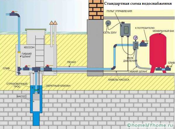
From a well, or other source, water is pumped into the main pipeline. To prevent its movement in the opposite direction, a safety valve is installed. Stop valves are installed in the right places. It is used for preventive maintenance, adjustment, replacement of failed blocks.
The water flows through the pipeline into a special container that performs several functions:
- accumulation and storage of a stock of liquid;
- creation of normal pressure in pipeline sections connected to consumers;
- damping of pressure drops when connecting local water supply to centralized networks.
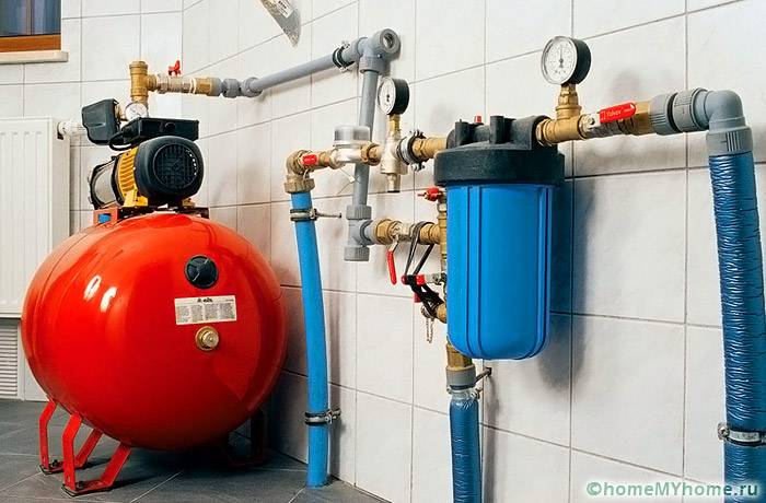
The main working element of such a container is a flexible partition. But the initial pressure in the tank itself is created by the pump. With the appropriate equipment, it is controlled from a special remote control. Data from the pressure switch for the accumulator is received there.
Above is a part of the smart home class diagram. It connects to the general control system. In practice, more economical solutions are often used.
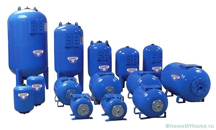
To successfully solve the designated tasks, the following designs of accumulators are used:
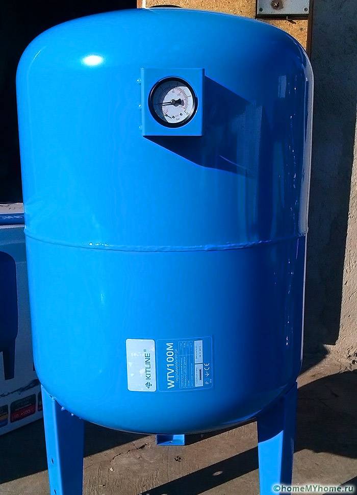
- A durable tank is created with elements that are useful for firmly fixing it on a horizontal or vertical plane.
- Metal housings are protected against corrosion by special coatings. They are designed for pressures up to 6 atm. and higher.
- A rubber membrane is inserted inside.
- A built-in spool is used for adjustments and adding and bleeding air. A special valve is mounted in large containers.
- To increase consumer characteristics, a layer of enamel, ceramics and other chemically neutral compounds is created inside the tank. For systems with drinking water, completely safe types of rubber are used.
Note! If a hydraulic accumulator is purchased for a heating system, attention should be paid to the suitability of the model for working with liquids at elevated temperatures.
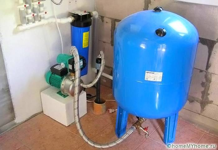
This picture shows another important element, the flow filter. It prevents the ingress of mechanical impurities, damage to the relay and blocking of its drive mechanisms. The increased tank capacity is useful not only with high daily consumption. It will reduce the number of pump starts / stops, which will have a positive impact on the longevity and reliability of the system.
In the standard procedure for calculating the volume of the tank (OB), the following formula is used:
OB = 16.5 x RV / KV x CD x 1 / DVKwhere:
- PB - consumption in liters per minute. They use the sum of all needs, household, cooking, sanitary and other.
- Kv - the number of starts of the injection pump for 60 minutes. It is recommended to select the parameters in such a way that the number of such starts does not exceed 8-10 for a corresponding period of time at maximum consumption.
- CD - complex pressure coefficient. It is calculated by the formula Dvk x Dvyk / (Dvk - Dvyk). Here Dvk and Dvyk are the levels of maximum and minimum pressure, according to which the pump is switched on and off.
- DVK Is the pressure that develops in the part of the tank where the air damper is located.
In order not to embarrass yourself with a year-round residence, a family of three is enough for a tank with a capacity of 40-60 liters. Such advice is given by specialized specialists. In fact, it is better to make a more accurate calculation with the above method. The results obtained should be increased taking into account the visits of guests, other situations, accompanied by increased water consumption. Such an approach will help to purchase a hydraulic accumulator for water supply, the price of which will correspond to the technical characteristics and needs of future users.
Placing the tank at the highest point in the structure will use the force of gravity. But it must be borne in mind that the room must be reliably protected from adverse external influences. It maintains temperatures above 0 ° C all year round.
Remember to increase mechanical stress. A large water tank weighs a lot, so sometimes additional reinforcement of the structural frame is required. For these reasons, large tanks are often installed in the basement.
Related article:
Adjusting the water pressure switch for the pump... A practical guide for the correct setting of the pressure switch for the pump with photo and video examples in a special publication.
How to install a pressure switch for a hydraulic accumulator
Before carrying out work steps, it is necessary to clarify the general requirements. To water supply system functioned in the optimal mode, the pressure difference for turning on and off the pump is set within the range from 0.9 to 1.8 atm. Exceeding it will increase power consumption.
To calculate how much pressure should be in the hydroaccumulator (DGA), use the formula DHA = (B + 6.5) / 10where:
- IN - height. This distance is taken from the central axis of the tank to the highest point at which the water is withdrawn.
- 6,5 - this digital factor takes into account the height of a particular building. For example, a typical cottage (2 floors) is taken.
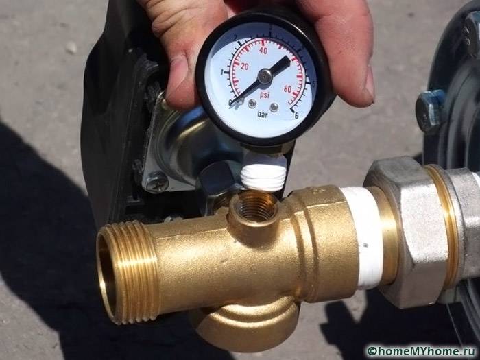
Note! In the absence of standard equipment, you will need an appropriate measuring device.
The process of connecting a pressure switch to a hydraulic accumulator
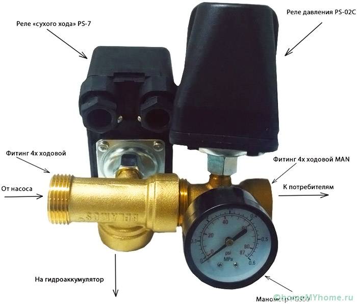
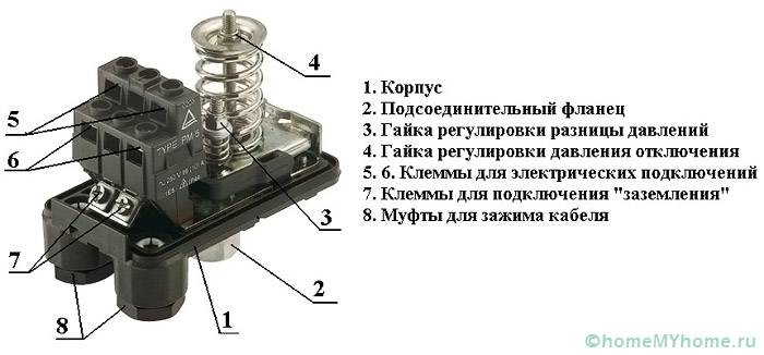
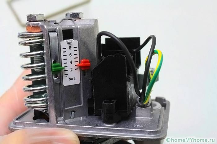
For study, this article covers mechanical pressure switchI am for the accumulator. This design is repeated in modifications by different manufacturers, with relatively minor changes.
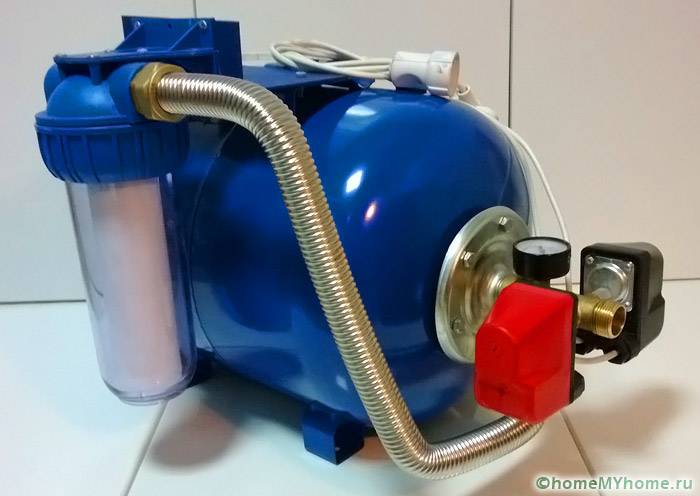
This product is connected to the assembled water supply system. Flexible tubing designed for the appropriate pressure levels can be used for placement in a convenient location. Transition fittings are used if necessary. Upon completion of installation, check experimentally the tightness of threaded connections.
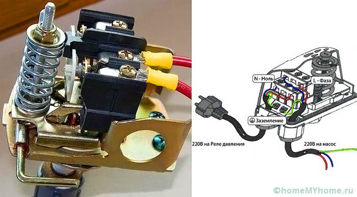
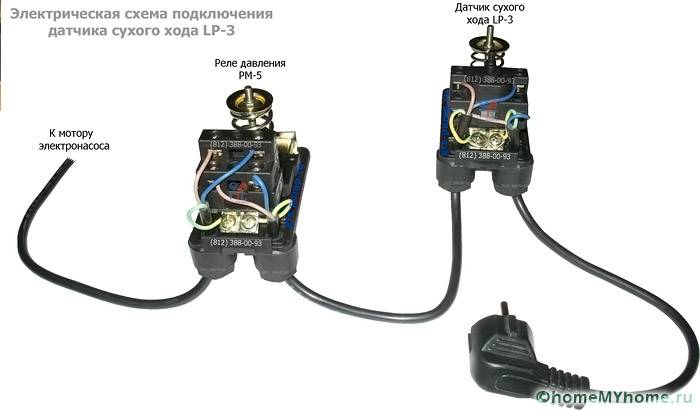
The electrical connection can be made directly in the pump supply circuit. Use wires designed for the corresponding power. To eliminate errors, it is recommended to use products with color braids. The ground standard is a combination of yellow and green. The electric motor is connected to a 220 V network through an automatic machine, which provides quick disconnection in the event of a short circuit.
All electrical work is performed with the voltage disconnected. It is necessary to exclude accidental voltage supply during the process of adjusting the pressure switch for the accumulator.
Accumulator pressure switch setting
Use the following algorithm:
- Turn off the pump and remove the water.
- Turn on the equipment and increase the pressure, followed by draining the fluid. Record the motor on / off levels.
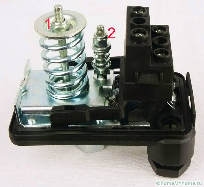
- The threshold at which voltage is applied to the engine is increased with a nut on a large spring (clamp it).
- The opening level of the relay contacts is adjusted by the height of the small spring.
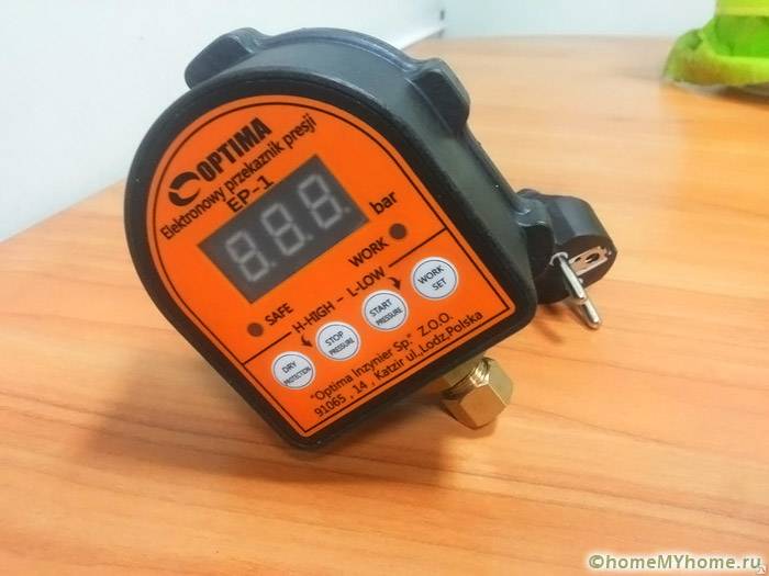
Consult the manufacturer's instructions for how to set up the electronic pressure switch for the accumulator.
Conclusion
When using the information in this article in practice, do not forget about an integrated approach. The water supply system performs its functions efficiently if all components are purchased, installed and configured correctly.
Video: setting the pressure switch


